
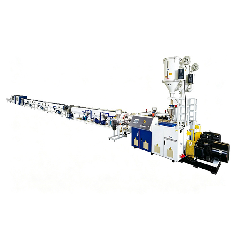
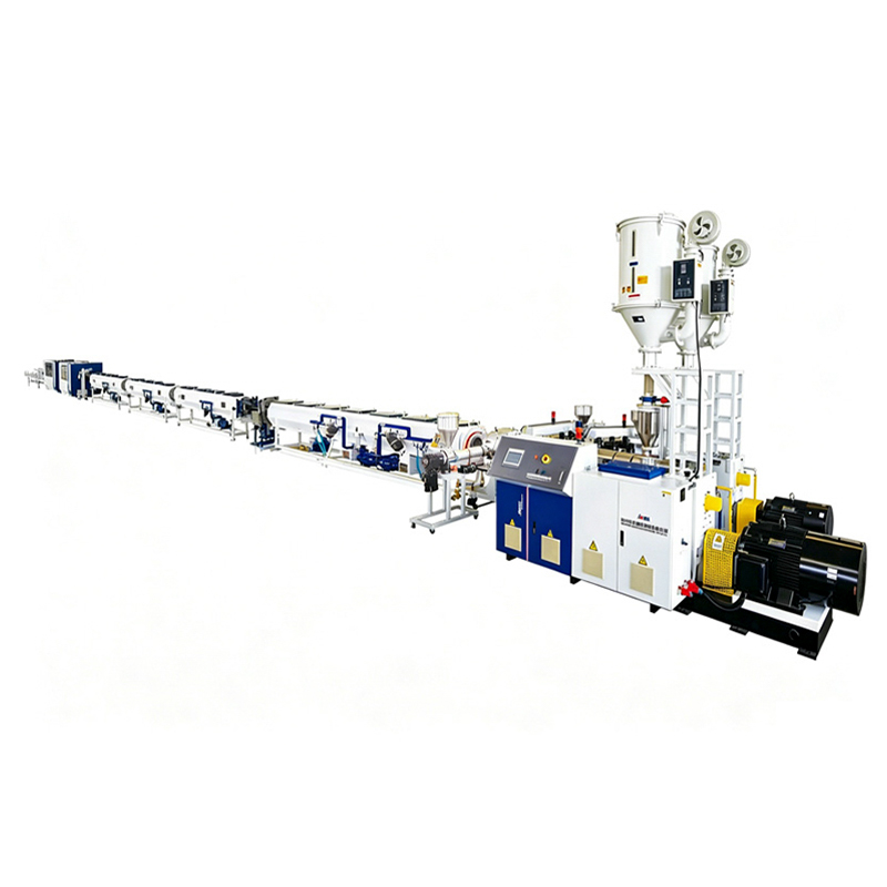
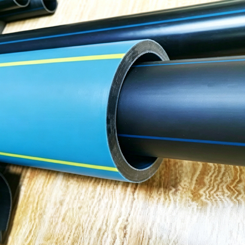
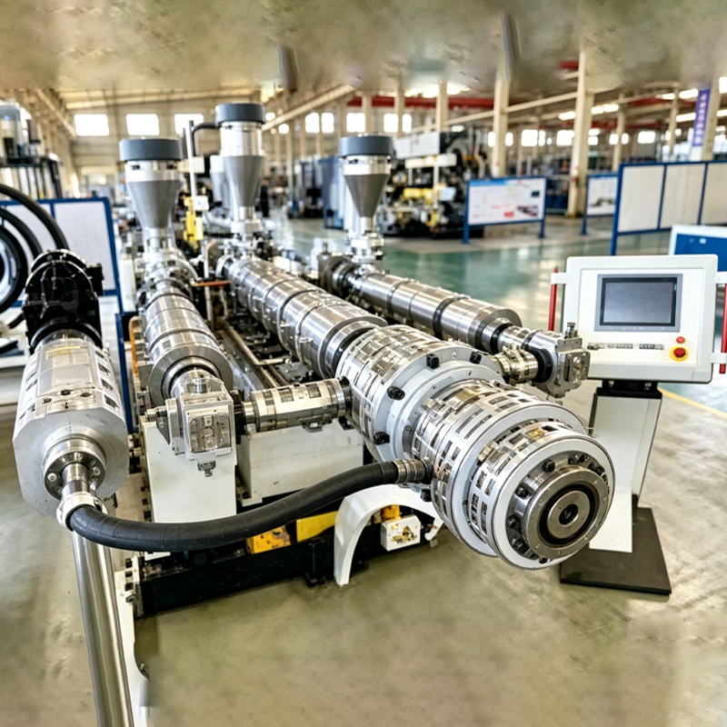
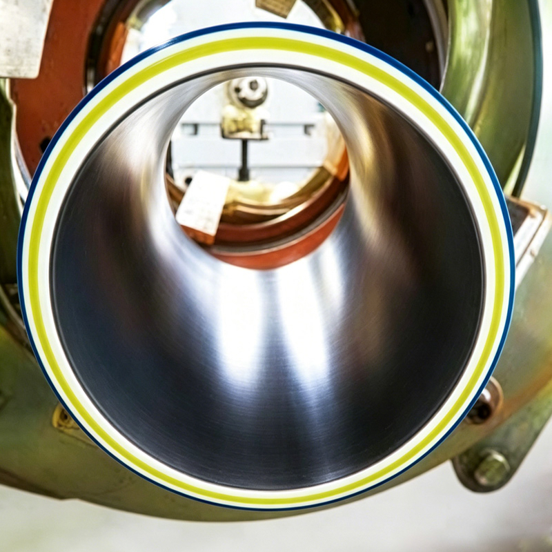
Jwell's multi-layer HDPE solid-wall pipe co-extrusion line is specifically designed to produce multi-layer HDPE solid-wall pipes for demanding infrastructure and industrial projects. Thanks to co-extrusion technology, different formulations can be used for the inner and outer layers (e.g., virgin material for the outer layer + recycled material or color masterbatch for the inner layer) without compromising performance.
Typical applications:
|
Industry |
Pipe Diameter Range (mm) |
Common Models |
|
Municipal water supply and drainage |
Φ75–Φ630 |
JWPEG-250, -315, -450, -630 |
|
Gas transmission (PE100) |
Φ20–Φ315 |
JWPEG-110, -160, -250, -315 |
|
Industrial slurry and chemical transport |
Φ50–Φ450 |
JWPEG-160, -250, -315, -450 |
|
Mining and tailings treatment |
Φ160–Φ630 |
JWPEG-450, -630 |
|
Submarine or trenchless installation (high stiffness) |
Φ315–Φ630 |
JWPEG-630 |
Real-world case: A water authority in Southeast Asia used the JWPEG-450 (diameter range Φ160–450 mm, capacity 740–810 kg/h) to produce three-layer HDPE pipes for a 25 km raw water transmission line. The inner layer used high-grade PE100 to reduce wear, while the outer layer used UV-resistant black compound. The line ran continuously for 18 months with material waste below 1.5% – directly attributed to precise co-extrusion control.
Our JWPEG series delivers quantifiable benefits over single-layer or conventional twin-screw lines.
A. High output, lower energy consumption per kg
Example: JWPEG-630 has a capacity of 1200–1240 kg/h, total main motor power 250+75 kW.
Energy efficiency ≈ 0.27 kWh/kg – leading in its diameter class.
Compared to older extrusion lines (typically 0.35–0.40 kWh/kg), our users report 15–20% electricity savings.
B. Wide diameter range covered by one line
Thanks to optimized screw geometry and downstream sizing equipment, each model covers a wide pipe diameter range.
|
Model |
Pipe Diameter Range (mm) |
Reason for flexibility |
|
JWPEG-63 |
Φ16–63 |
JW65/33+45/25 – smaller extruder, fast size change for thin-wall pipes |
|
JWPEG-250 |
Φ75–250 |
JW60/40+45/33 – low-speed high torque, for thick-wall pressure pipes |
|
JWPEG-630 |
Φ315–630 |
JW90/38+65/33 – two-stage cooling, suitable for large diameter pipes |
C. Multi-layer co-extrusion without delamination risk
Parallel extruder configuration (e.g., 65/33 + 45/33) ensures perfect melt bonding. The main extruder (larger) supplies the core layer, the co-extruder (smaller) provides inner/outer skin layers. This design eliminates air pockets and weak interfaces – critical for gas pipes.
D. Real-time process stability
All models are equipped with:
Gravimetric metering unit (optional but recommended)
Melt pressure and temperature sensors in the adapter zone
Self-centering die (standard on JWPEG-315 and above)
Example: A Turkish pipe manufacturer switched from a single-screw line to the JWPEG-315 (diameter range Φ110–315, capacity 550–610 kg/h). Their ovality dropped from 2.8% to 1.2%, and they passed EN 12201 hydrostatic tests on the first try.
To ensure every meter of pipe meets ISO 4427 / EN 12201 / ASTM F714 standards, we follow strict online in-process and post-production testing regimes.
Online process monitoring (real-time)
|
Parameter (inner/outer/core wall thickness) |
Control method |
Tolerance |
|
Wall thickness |
Ultrasonic scanner (8-axis) |
±0.1 mm |
|
Outer diameter and ovality |
Laser micrometer |
±0.5% of nominal OD |
|
Melt temperature |
3 thermocouples in adapter |
±3°C |
|
Extruder screw speed |
Closed-loop PID control |
±0.5 rpm |
Example: On the JWPEG-450, the ultrasonic scanner checks wall thickness distribution every 200 mm. If the inner layer deviates by more than 0.15 mm, the co-extruder speed is automatically adjusted.
Offline tests (per production shift)
We recommend the following test schedule:
|
Test item |
Standard |
Frequency |
Equipment |
|
Hydrostatic test (20°C, 100h) |
ISO 1167 |
Every 500 m |
Burst testing machine |
|
Melt flow index (MFI) |
ISO 1133 |
Once per shift |
Melt flow indexer |
|
Oxidation induction time (OIT) |
ISO 11357 |
Every 8 hours |
DSC |
|
Carbon black dispersion |
ISO 18553 |
Per raw material batch |
Microscope |
|
Interlayer peel strength |
ISO 13954 |
Every 200 m |
Tensile tester |
Real-world case: A Canadian mining company using the JWPEG-630 required peel strength between the wear-resistant inner layer and HDPE core layer > 200 N/25mm. Our line consistently delivers 230–250 N/25mm. The key is a special flange adapter with static mixer – a detail we include in the JWPEG-630 configuration.
Finished pipe pre-shipment checklist
Appearance: no bubbles, pits, or black spots.
Dimensions: measure outer diameter, inner diameter, wall thickness at 4 points per meter.
Marking: permanence and legibility (per ISO 4427).
End squareness: ≤ 1.5 mm per 100 mm diameter.
| Model | Pipe Spec(mm) | Extruder | Main Power(kw) | Output (kg/h) |
| JWPEG-63 | φ16-63 | JWS65/33+45/25 | 55+15 | 170-220 |
| JWPEG-110 | φ20-110 | JWS65/33+45/33 | 75+22 | 250-300 |
| JWPEG-160 | φ50-160 | JWS60/40+45/33 | 90+22 | 400-500 |
| JWPEG-250 | φ75-250 | JWS60/40+45/33 | 110+22 | 450-510 |
| JWPEG-315 | φ110-315 | JWS75/38+45/33 | 132+30 | 550-610 |
| JWPEG-450 | φ160-450 | JWS75/38+65/33 | 160+55 | 740-810 |
| JWPEG-630 | φ315-630 | jWS90/38+65/33 | 250+75 | 1200-1240 |
The following are the five most frequently asked questions from customers – answered directly with our parameters and field experience.
Q1: Can I use recycled HDPE as the middle layer on the JWPEG-250?
A: Yes – provided the recycled material's MFI is no more than 0.5 g/10min higher than that of the outer layer virgin material. The JWPEG-250's main extruder is 60/40 (screw L/D 40D), providing excellent shear and degassing capability. We recommend installing a melt filter (150 μm) on the recycled material stream. A Chilean pipe manufacturer used 35% post-industrial recycled material in the core layer on their JWPEG-250 and still maintained full EN 12201 certification.
Q2: How do I change from Φ110 to Φ250 pipe diameter on the same line?
A: On the JWPEG-315 (diameter range Φ110–315), size change takes about 2.5 hours:
Change the tooling and sizing sleeve (quick-change type as standard).
Adjust the cooling tank length (first tank fixed, move the second tank).
Update haul-off speed via the touchscreen recipe (Siemens PLC stores 100 recipes).
Run automatic wall thickness calibration (built-in algorithm).
No need to change the extruder screw – the 75/38 screw is optimized for the whole diameter range.
Q3: What is the minimum wall thickness the JWPEG-450 can produce?
A: For Φ450 mm pipe, minimum wall thickness is 13.5 mm (SDR 33), maximum 42 mm (SDR 11). The 160 kW main motor provides enough torque to handle high back pressure. We have successfully produced 45 mm wall thickness pipe (for mining slurry) at 720 kg/h – slightly below the nominal 740–810 kg/h, which is normal for thick-wall production.
Q4: My output is lower than the specification (e.g., only 500 kg/h on a JWPEG-630). What should I check?
A: Follow this checklist (based on field troubleshooting at a factory in Vietnam):
·Screw speed – is it above 85% of maximum? The JW90/38 extruder requires >75 rpm to reach 1200 kg/h.
·Melt temperature – too low (<195°C) increases viscosity and reduces output. Target 200–215°C for HDPE.
·Screen pack – if using 120 mesh screen, change every 8-10 tons of production. A clogged screen can reduce output by 30%.
·Hopper bridging – recycled material often blocks the feed throat. Install a pneumatic knocker.
After correcting these issues, the Vietnamese customer consistently achieved 1180 kg/h output.
Q5: How to prevent interlayer delamination in multi-layer pipes?
A: Delamination usually occurs at the adapter flange. The solution has three points:
·Temperature matching – keep the melt temperature difference between the two melts within 5°C. Our control system displays melt temperatures from both extruders in real time.
·Pressure balance – the co-extruder's outlet pressure should be 80–90% of the main extruder's pressure. Our JWPEG-160 and larger models come with pressure balancing valves.
·Adapter geometry – use a spiral mandrel die (standard on JWPEG-315 and above) rather than a simple spider die. The spiral type achieves laminar melt flow and avoids weld lines.
A Malaysian gas pipe manufacturer using the JWPEG-315 passed 500-hour hydrostatic tests with no delamination – their outer layer OIT was 45 minutes, inner layer 42 minutes, proving perfect bonding.
Q6: What is the minimum and maximum pipe length I can produce with one line?
A: There is no fixed limit. The line runs continuously, and you can cut any length from 6 m to 12 m (standard) or up to 18 m on request. The haul-off and saw are adjustable. For example, a JWPEG-250 user in Egypt cuts 12 m pipes for water networks without any problem.




Pipe Extrusion Production Line
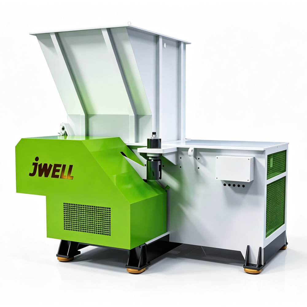
Plastic Shredder Crusher Machine

Tel: +86-19057068112

E-mail: [email protected]

Company Address
No. 128 Qingfeng Road, Xieqiao Town, Haining City, Jiaxing City, Zhejiang Province

19057068112

 English
 русский